Revised: 5/20/2013 Subject To Revisions
Tender Truck Wheel Design
Blog Posting Resumed
It has been about six months since the last update of this post. The author has three projects underway and more recently my engineer son has injected two of his projects needing attention. Consequently this project has been lagging attention. My priorities are 1) The ABS 3D printer 1/24th scale model USRA Mikado, 2) Model wind waggon and 3) CNC metal model Mikado, this blog. To see progress on my models see the links to my other blogs.
Overview of Design
The truck wheel has a contoured cross-section. On the prototype wheels such as this are cast to roughly net shape and critical dimensions machined. For the model the author decided that the wheels will be machined from round bar stock aluminum using the lathe. An alternative would be to machine the part from flat bar stock using the milling machine. The milling machine could also turn the wheel using the 4th axis rotary table. Contouring on the milling machine would require a ball-end mill which the author has not yet purchased, so it was decided to proceed with the lathe option. The lathe makes a lot of sense for a wheel since lathes make round parts which of course the wheel is.
The first step was to design the wheels in the Alibre 3D CAD program to match the plan drawings as closely as possible. Below are shown the inside and outside isometric views of the resulting 3D designs. The Alibre software also produces blueprint type drawings of the part and considerable detail views of the various cross section portions.
3D CAD Inside View of Tender Truck Wheel
3D CAD Outside View of Tender Truck Wheel
3D CAD Design Flow
Since the part will be machined from round stock, the design flow began by creating a piece of round stock from which the part will be machined. One and one-quarter inch round stock was selected. A length of about two and one-half inches was cut from a three-foot bar. The sequence of lathe cuts were ordered in the CAD design as in the set of CAD isometric views shown next.
2 1/2" Piece of 1 1/4" Diameter Round Stock
Round Stock Piece Face Cut to Square Surface With Lathe Axis
Small Pilot Hole Drilled With Center Drill Held In Tail stock
Center Hole Was Enlarged With Successively Larger Drill Bits
Final Hole Size Made With Boring Tool On Lathe Cross-Slide
Initial Interior Contour of Wheel Outside
Exterior Contour of Wheel Outside and Cut-Off
Cut-Off Wheel Part With Completed Outside Contour
Inside Wheel Face Cut To Square With Lathe
Inside Wheel Contour After Machining
Fabrication Experiences
First Effort
After designing the tender wheel the author wrote g-code programs for the several steps and began to fabricate the first wheel.
Cutting the outside contour on CNC lathe
Using the lessons learned fabricating the axles, the steps outlined previously in the design discussion were followed using separate programs for the two sections of the inside contour, another for the rim and outside of the flange and another for the outside contour. Each program required a careful alignment of the tool relative to the lathe axes, x for the cross slide and y for the lead screw zero positions.
The x axis zero was done using a dead center inserted in the Morse taper of the lathe. The y axis was done relative to the work face. Programmed cuts were then made to remove material in 10 mil layers until only about 5 mils remained above the contour. A final pass was then made to follow the outline.
The inside contour had a portion that was parallel to the y lathe axis at the inner diameter of the rim. In order to cut that the lathe tool was angled outward about 15 degrees. The rest of the contour from the axle to the rim edge needed a tool angle almost parallel to the y axis. Finally the side of the rim, rim and outside of the flange needed a tool angle of about 80 degrees relative to the lathe axis.
Each tool setup had it's own g-code routine to cut the appropriate portion of the contour. Three different tool angles and programs were required then to do the outside contour. In the photo above the tool angle is about 15 degrees relative to the lathe lead screw axis and used to machine the portion from the axle to about mid-way between the axle and rim.
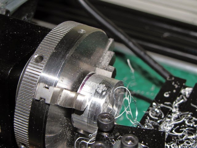
Cutting the inside contour on the CNC lathe
The above photo shows a wheel with the first portion of the inside contour from the axle to about half way to the rim. The wheel is held in the lathe three jaw chuck by the rim. The tool was nearly parallel to the lathe lead screw y axis for these passes. A separate tool angle run was needed to complete the overall inside wheel contour.
Finished wheel outside face
The photo above shows the wheel outside contour. The rough region about two-thirds out from the center is the region where the tool angles were changed.
Wheel inside face
The inside contour of the wheel above experienced side and bottom scraping on the tool due to the wheel radius and tool vertical angles. It was not good as the scraping changed the overall contour and but extra stress on the wheel leaving marks from the chuck on the rim.
The author concluded that perhaps another approach was needed to better fabricate the wheels. The approach next tried was to take into account the tool angle relative to the work modifying the contour so that a single program could be used to do the entire contour from the center to the rim. The rim and flange would be a separate run. This would require just three runs and programs. One for the inside contour, another for the outside and one more for the rim and flange.
Next Attempt
First attempt wheel outside contour with rough region
Second attempt wheel using continuous contour cutting
The second attempt came out much better. Incidentally, the hole in the center was drilled first after truing up the face of the work piece. The hole is 1/4 inch. Two runs were needed for this face, one for the inside contour from wheel center to rim and another for the rim and flange. The finish is good and no interface region exists between the portion near the axle and that near the rim sidewall. The tool used was a custom shape with about a 45 degree tool angle and a 8 to 10 degree tool sidewall angle. This resulted in a tool with sufficient clearance on sides and bottom to avoid scraping and gouging the part.
Second (left) and first (right) attempts
The interior contours are nearly identical with no evidence of tool scraping on the part. The center holes were done differently as well. The part on the left was drilled using a 1/4 inch drill on the lathe while one on the right was bored using the boring tool. It was difficult to bore the part correctly at 1/4 inch as the backside of the boring tool would cut material off and enlarge the hole excessively. After trying to modify the tool and other attempts on test pieces, the lathe boring tool was not used. It appears to be more suited to larger holes.
Second attempt (left) with first attempt (right) and axle
The first wheel has an overly large hole which is way too loose on the wheel. Even the second attempt wheel is slightly loose, but is much closer. The author contemplates keeping the wheel hole as is with the drill size and modify the diameter of the corresponding portion of the axle and make new ones to fit. The idea is to have them the same size and press the wheels on the axles.
Temporary assembly of wheels on axle
The picture above shows the wheel and axle assembly. The design is planned to fit on existing G gauge track. The author does not plan to insulate one side as is done for model trains since the model being built is principally a display model. The use of G gauge track is simply to provide a ready source. The author's other model locomotive project (see blog links at the top of page) is made of ABS plastic on a 3D at 1/2 inch per foot scale and requires a wider gauge.
Now that the wheel fabrication is OK the author plans to make a full set of eight for the tender trucks plus a couple of spares and a new set of axles with slightly larger diameter wheel mounting points. The modification is very small, only a slight increase is needed.
Third Pair Fabrication
Now that an approach and de-bugged G-Code is available, the author cut two short ~ 5/8" blanks from the 5/16" diameter 6061-T6 aluminum bar stock. The general approach is to face the blocks, cut the outside contour, drill the center hole, reverse the block in the lathe and cut the inside contour, trim as required.
Face cutting the wheel blank block
Face cut nearly complete
Final pass
Wheel blank after face cut
Once the face cut is done on one side the blank can be mounted more squarely in the lathe ready for the contouring cut.
First pass of wheel outside contouring cuts
Contouring cut showing continuous chip of material being removed
Another deeper cut
Nearing final contour pass
Final outside wheel contouring pass
Finished wheel outside contour
Contouring is done using CNC G-Code programming which makes a series of passes removing about 0.01" of material each pass. The program controls the depth of cut at the various diameters making sloping and radius cuts as needed.
First cut of the wheel rim and flange portion with standard lathe cutting tool
Mid-way through the wheel tire and flange cut
Completed wheel tire and flange cuts
The contour does not include the wheel tire and flange portion which is cut using a separate G-Code program with a standard right hand cutting tool. A separate set-up and G-Code program is used that makes possible the rounded corners and patterns for the flange.
The next sequence is to manually bore the center hole. This is done in stages; center drill to guide the first drill, drill an approximately 0.1" diameter hole, drill a series of larger drill sizes ending up with a 0.250" drill for the final size. Drilling is done by mounting the drill bit in the tail stock chuck and manually advancing the drill bit into the work as the lathe turns. The drill is advanced about equal to the drill diameter then backed out to clear the chips and advanced again about another drill diameter and so forth.
Machining lubricant is used to assist the chips in being pushed out of the hole along the drill grooves. The rate of advance is slow to achieve a good clean hole.
Center drilling to a small depth to guide the first drill bit
First drill bit is about 0.1" diameter requiring about five plug and withdraw steps
Slightly larger drill bit is then used to enlarge hole to about 0.15"
Larger drill yet used to enlarge hole further
Still larger drill bit enlarging hole
Hole diameter is getting closer to final size
Largest size drill in author's drill index used next, 0.228"
Final drill is 0.250" diameter
View of drilling setup on lathe
Final hole showing chips coming out of hole along drill flutes
Final hole size complete
After drilling the wheel block is removed from the lathe in preparation for reversing the mount and cutting the inside contour.
Wheel block with outside contour and hole drilling complete
Inside contour partially cut
Inside contour complete, flash on flange to be trimmed yet
Wheel with flash removed
The inside contour cut is done by mounting the wheel blank in the chuck on the wheel tire. A separate G-Code program is used to make the contour cut. The cut is continuous to the tip of the flange. This cut generates a thin flash on the flange tip which is removed using a file run along the tip as the lathe turns.
Completed wheel showing outside contour
Completed wheel inside contour
Pair of completed wheels, inside contour
Pair of completed wheels, outside contour
With this last series of fabrication steps the author is satisfied that the wheels can be duplicated accurately and more can now be made to populate the model tender. New axles will be needed since the final bores are slightly larger than 0.250", both wheels measure 0.253" within 0.00025". New axles with a press fit size are needed to work with this wheel configuration. Axles made previously are 0.250" and a bit less. They will not work correctly and cannot be enlarged. The next post will describe the new axle fabrication processes.