Revised 8/18/2012 Subject to Revisions
Tender truck axle design was done using the Alibre 3D CAD program which produced the following 3D isometric view. The axle is a bit over 2.8" long and a bit over 1/4" diameter at the largest point. The outermost ridge is a retainer for the journal bearings which ride on the smallest diameter portion next to it. The diameter then increases in two steps to the wheel hub region which then ends in a narrow ring that stops the wheel at gauge width. The central portion consists of a taper down to a short section at the center. The axle is symmetric repeating all portions in mirror image to the other end.

Shown next is a snippet of the CNC G-Code text used to drive the Sherline Model 4400 lathe. Due to the shape of the normal cutting tool selected it is necessary to have a down ramp when transitioning from a larger diameter to a smaller in the direction of the lathe feed. When going from a smaller diameter to a larger in the direction of the feed a vertical wall is possible. That means the part will need to be reversed and run through the same program to convert the down ramps into vertical edges.

The G-Code program is many lines long with sections devoted to:
- Trimming the stock material radius from 0.15625" (5/32") to 0.1310", the radius of the inner wheel stops, largest portion of the axle.
- Cutting all portions except the inner wheel stops to 0.1252"
- Cutting the central tapers in two steps. Tapers down from 0.1252" to 0.1040" over 0.5667" then tapers up from 0.1040" to 0.1252" at the inner wheel stop at the other side
- Cutting the journal stop radius across the journal region to 0.1163"
- Cutting the journal bearing radius to 0.0941"

The stock material work piece begins as a ~5" length of 5/32" stock (radius 5/32"). The rod is trimmed at the ends and center drilled with a cone to fit the active rest, the round black part with a cone centered on the work rod at the right in the above photo. The active rest holds the end of the rod steady during machining. It is active in that it is a ball bearing mounted cone that rotates with the work eliminating most the turning friction. The cutting tool in the holder on the cross slide is the standard "normal" tool which has a taper away from the work on the heel of the tool. During cutting the tool will travel from right to left so the sharp point edge of the tool chisels away the unwanted material.
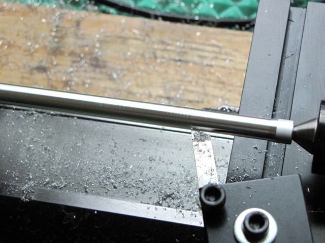
During the first cut the diameter of the work is reduced by 0.040" as the tool makes a radius reduction of 0.020". In the above photo the author was testing that portion of the program and ran it a second time to skim the work, hence no chips where coming off behind the tool. Chips are seen down below.

The photo of the computer monitor shows a tool tip path tracing from the G-Code showing the cut design for the inner tapers, one down and the other up. The total cut is made in two runs to divide the total cut depth into halves to minimize the chip size and torque needed.

The photo next shows the resulting tapers. The tapers closely match the design as expected. The ability to make such features is a strong suite of CNC.

Also shown are two oops pieces at the top of the set. These occurred when the author attempted to make manual cuts and forgot which way was in and out on the cross slide.
The three at the middle are axles that followed the program but did not have sufficient down ramp length or exhibited different resultant diameters at opposite ends. The different diameters were determined to be the result of slight misalignment of the head stock relative to the feed slide. For the last run on the photo at the bottom, the Sherline manual adjustment procedure was done which brought the opposite end diameters to within 1.5 mils.
It occurred to the author that using parameters and math in G-Code could perhaps compensate for the machines slight misalignment values. The author will experiment with that approach and see whether it will work OK. The use of parameters will also permit automatic adjustment for factors such as the exact diameter of the work bar. Raw stock aluminum bar is not exact in dimensions. The bar used here was about 0.004" oversize in diameter. The author was able to compensate for that during machine set up by locating the cut axis zero point 0.002" closer to the work outer diameter. This worked OK but revealed the fact that the outer diameter was larger than the diameter close to the chuck. That was caused by the slight outward angle of the headstock. The headstock is keyed so only very tiny adjustment could be made. That adjustment reduced the error but could not eliminate it. The procedure to do the alignment per Sherline handbook resulted in a 0.002" diameter difference over a part feed distance of 1.5".

The first fairly good axle is shown below. Although it has errors of section diameters for the wheel hubs and journal bearings of ~ 0.0025", it will suffice for now. The author will continue to improve his techniques in an attempt to better the results in future. The final axle is separated from the work bar using the cut off tool that comes with the Sherline machine shop set up. After cut off a small tip was removed be chucking the part up and cutting it off using the normal tool. The tip is the result of slight error in the height of the cut off tool relative to the center of rotation.

The next step will be fabricate more axles using improvements in technique and perhaps G-Code improvements as well attempting to reduce the errors to ~ 0.001" or so in critical diameters, wheel hub and journal bearing regions.

The four candidate axles were separated from the turning part with the cut-off tool and marked to prepare for measurement data gathering.

Pictured along side a ruler gives a sense of the size of the four axles, just a bit less than three inches long and a bit over 1/4 inch at the maximum diameter. Eight journal bearing surfaces and eight wheel hub regions will be measured being the most critical.

Journal statistics are based on 21 measurements of each journal region. The extreme projection at the average - 3.3 sigma, the minimum, the average, the maximum and the average + 3.3 sigma are plotted above for each of the eight sets of 21 readings. The first two journals are for axle #1, the next two for axle #2 and so forth. Since the axles were numbered after separation and without maintaining trace back to the order of fabrication no meaningful analysis of the order can be made. I do know that a couple axles were made after adjusting the alignment of the lathe headstock which was done to reduce the difference in diameter near the headstock relative to that near the tailstock.
The test piece made after adjustment showed a difference of about 1 mil every 1.5" or so. Further work will be done to adjust the lathe if possible. If it cannot be brought into better alignment then g-code software will incorporate parameters and calculations to adjust based on distance along the piece. This may allow further reduction in errors.

Statistics for the wheel hub regions of the axle are shown above. The results are similar and show a similar pattern to the journal pattern above. Since both journal and wheel hub information is based on the same parts and presented in the same order, inferences can be drawn about the relationship of the journal diameters to that of the wheel hubs. In general both show a similar tendency to very about the same amount in the same direction.
It was observed that the reversal of the axles and use of the same program to square the edges worked generally, but that the diameters definitely have two different regions. This is fully attributed to the fact that when cutting the axle mounted in reverse the difference in diameters is cut into the part where the slopes were applied in the initial cut. Another possible error is caused by the operator since it is necessary to re-align the axle with the cutting tool in the y or feed direction. This shows up as a variation in the width of the journal cut. Statistics were not taken on that parameter as it is not nearly as critical as the diameters.
Since the wheel hub diameters vary it is not possible to provide a press fit for the wheels unless the ID of each wheel is custom cut to match the respective axle end. At this point I do not have a good idea of the variation that will occur with the ID of wheel hubs. They will have variations as well, but at this point it is not known how much. I'm still debating insulating one side of the axles by mounting the wheel there with a plastic spacer. The two sides would require different wheel designs one having a larger ID for the insulator.
The reason for this is to allow the finished locomotive to run on conventional g scale rail without shorting out the power packs. I'm not sure that the locomotive will be powered and how it will be done at this point. That is another decision that must be made. By insulating the tender truck wheels one side will be insulated while the other will electrically connect to the tender frame through the trucks.
The journal bearings are another matter to be faced. If they are to conduct they must be made of a material compatible with a sliding fit on aluminum, either that or the axles will need to be re-made from a compatible material, steel or brass.


